







Why Are More Companies Choosing Integrated Robot Joint Modules?
In a conventional externally driven joint system, developers need to select and integrate multiple components, including the motor, gearbox, coupling, servo drive, and encoders. They must also handle mechanical alignment, cable routing, servo parameter tuning, and system-level commissioning.
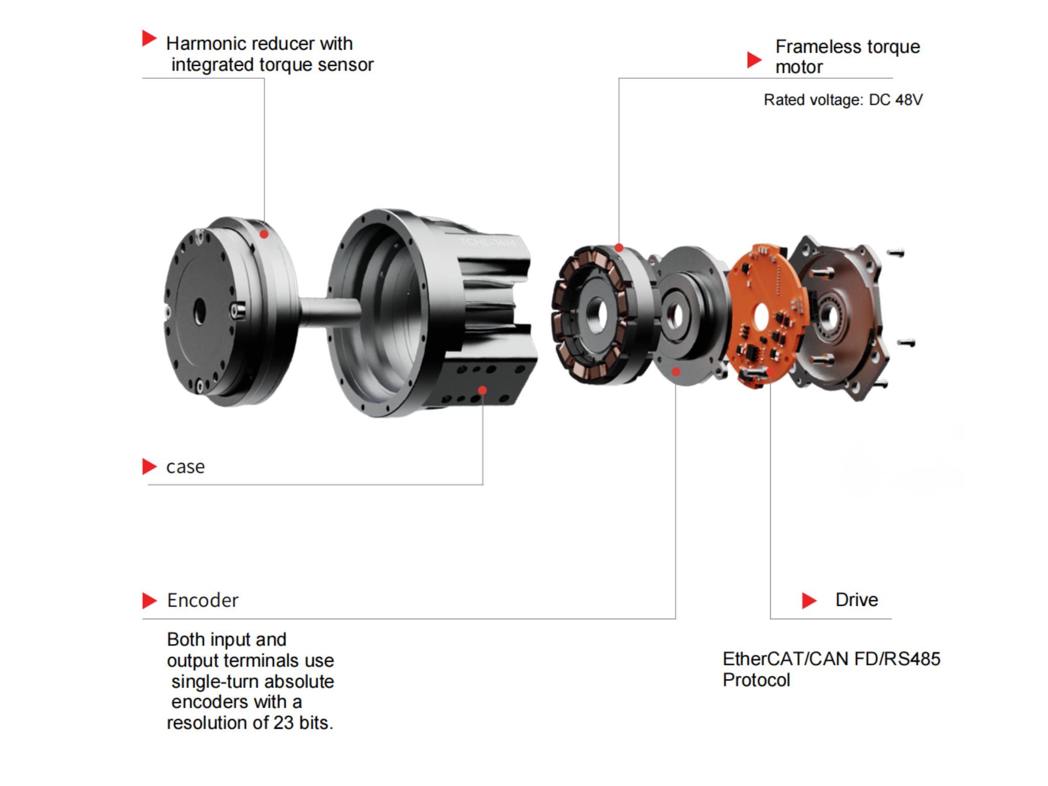
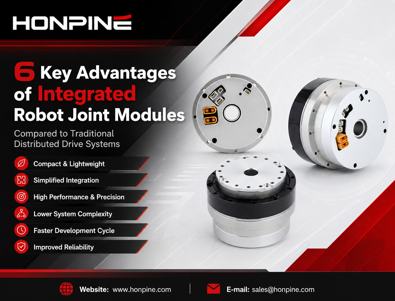
An integrated harmonic robot joint module combines key components into a single housing, including a frameless torque motor, harmonic reducer, crossed roller output bearing, FOC servo drive board, absolute encoders (single or dual), and an optional brake.
This integrated architecture can simplify mechanical design, reduce installation complexity, improve system integration, and shorten robot development cycles.
This article compares integrated robot joint modules with traditional distributed drive solutions from six perspectives: torque density and size, assembly reliability, motion control and safety, engineering development efficiency, practical applications, and potential limitations.
1. Higher Torque Density and Compact Design: Key Benefits for Humanoid Robots and Exoskeletons
Fewer Intermediate Mechanical Components
A conventional distributed joint system may require multiple additional components, including couplings, motor mounting brackets, gearbox adapter plates, external servo drive housings, and drive mounting brackets.
These components occupy additional axial and radial space while increasing the overall weight of the robot.
For example, the HONPINE HPJM-RI80-110-PRO-2 integrated robot joint module delivers a rated torque of 133 Nm with a housing outer diameter of 110 mm.
Compared with a distributed solution designed for a similar torque requirement, an integrated module can eliminate many separate mounting and transmission components. Depending on the motor, gearbox, drive, and structural design, the resulting system may achieve substantial reductions in installation space and component count.
Hollow-Shaft Integration for More Compact Robot Design
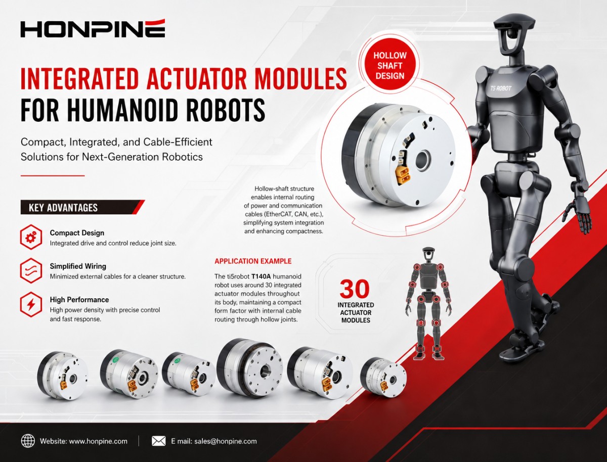
Integrated joint modules often feature a hollow-shaft structure, allowing power cables and communication cables such as EtherCAT and CAN to pass through the joint's central opening.
This eliminates the need to route all cables externally around the joint and helps create a cleaner internal layout.
Application example: ti5robot T140A Humanoid Robot
The ti5robot T140A humanoid robot uses approximately 30 integrated joint modules throughout its body. Cables for the arms and legs can be routed through the hollow joint structures, helping maintain a compact external appearance.
With a distributed drive architecture, separate servo drives and additional wiring would need to be accommodated throughout the robot's limbs. This could increase housing dimensions, complicate cable management, and add weight to moving structures.
Reduced Moving Mass and Improved Dynamic Performance
In robotic systems, the weight of moving components directly affects inertia and dynamic performance.
In a distributed joint design, additional motor brackets, adapter plates, and other mounting structures can increase the mass of moving links. When these components are positioned away from the joint's rotational axis, they can also increase the overall moment of inertia.
An integrated joint module consolidates the drive components within the joint housing, potentially reducing the number of additional structures required on the robot links.
This can help reduce moving mass and improve acceleration, response speed, and energy efficiency, depending on the overall mechanical design.
Application example: Lower-Limb Rehabilitation Exoskeletons
For lower-limb rehabilitation exoskeletons, device weight directly affects the physical burden on the wearer.
The HONPINE HPJM-RI60-80-PRO-2 integrated joint module provides a rated torque of 53 Nm. Its integrated design can help reduce the need for additional motor mounting and transmission components, supporting more compact and lightweight exoskeleton development.
With a distributed drive solution, external servo drives and mounting structures may require larger limb housings, increasing the weight that users must carry during walking and rehabilitation exercises.
2. Improved Assembly Accuracy and Reliability: Reducing Errors Introduced During Integration
Factory Integration and Calibration Reduce Assembly Risks
One of the major challenges of a distributed joint system is the precision required during mechanical assembly.
Developers must ensure correct alignment between the motor and harmonic reducer, properly install the encoder, and meet the required mechanical tolerances. Incorrect alignment or assembly can contribute to vibration, abnormal noise, accelerated reducer wear, and inaccurate encoder readings.
With an integrated harmonic joint module, key assembly and calibration procedures can be completed at the manufacturing facility before delivery.
Depending on the manufacturer's quality control process, these procedures may include:
Coaxial alignment of the motor and harmonic reducer.
Reducer assembly and preload-related adjustments.
Encoder installation and calibration.
Vibration and noise inspection.
Functional testing before shipment.
This transfers many precision assembly tasks from the customer's production line to the module manufacturer.
For example, some customers experience abnormal noise or vibration when the mounting flange flatness or locating features of their self-assembled joint system do not meet the required tolerances.
An integrated joint module with a standardized output locating feature, such as an H7/h7 fit where specified by the design, can simplify mechanical installation. The customer mainly needs to manufacture a matching load flange rather than assemble and align the internal reducer components.
Integrated Crossed Roller Bearings Reduce the Need for Additional Support Structures
Many integrated harmonic joint modules incorporate crossed roller bearings at the output end.
These bearings are designed to support combined radial and axial loads, allowing the external load to be supported directly by the joint module's bearing structure within its specified load limits.
In a distributed design, developers may need to add external support bearings to handle radial forces and overturning moments.
However, an improperly designed external bearing arrangement can introduce over-constraint, installation errors, vibration, and abnormal noise.
On the other hand, if adequate output support is not provided, excessive external loads may be transferred to components that are not intended to carry them, potentially affecting coupling life and reducer performance.
An integrated output bearing structure can simplify the mechanical design, provided that the module's allowable radial load, axial load, and moment capacity are suitable for the application.
Simplified Electrical Connections and Cable Management
Integrated joint modules can combine power, communication, and feedback interfaces within a more compact rear cover or connector assembly.
Depending on the configuration, available interfaces may include CAN, EtherCAT, and power connections. Some EtherCAT versions also support IN-OUT connections for daisy-chain communication between multiple joints.
In a distributed architecture, each motor may require separate power cables, motor encoder cables, output encoder cables, and connections to an external servo drive.
As the number of joints increases, the cable harness becomes more complicated and the number of connectors and potential electrical failure points increases.
For humanoid robots with dozens of joints, cable routing, connector installation, and maintenance can become significant engineering challenges.
Integrated modules can help reduce wiring complexity and simplify multi-axis system integration.
Application example: Five-Finger Dexterous Hands
The HONPINE HPJM-RI30-40-PRO-2 compact integrated joint module is designed for applications such as finger actuation in five-finger dexterous hands.
The internal space of a robotic finger is extremely limited. A conventional combination of a separate motor, coupling, and harmonic reducer may be difficult to accommodate within the finger structure.
By integrating key drive components into a compact housing, an integrated joint module provides a practical approach to designing small, multi-joint robotic hands.
3. Improved Motion Control and Safety Features: Integrated Drives and Encoder Feedback
Dual-Encoder Feedback for More Complete Closed-Loop Control
Some integrated harmonic joint modules support dual-encoder configurations, with one encoder on the motor side and another on the output side.
For example, the HONPINE HPJM-2E-EC dual-encoder version uses:
Motor-side encoder: Measures motor position and speed.
Output-side encoder: Measures the actual angular position of the output flange.
The two feedback signals allow the control system to monitor both motor-side and output-side motion.
This is particularly useful in harmonic drive systems, where elastic deformation under load can cause differences between motor-side position and actual output position.
By measuring the output flange directly, a dual-encoder configuration can improve output position feedback and help compensate for transmission-related position deviations.
In a distributed system, achieving similar functionality requires separate motor and output encoders, additional wiring, compatible drive hardware, and the development of the corresponding feedback and control logic.
An integrated dual-encoder module can simplify this process by providing a more standardized hardware and feedback architecture.
Integrated Position, Speed, and Current Control with Fault Protection
An integrated servo drive may support three primary control loops:
Position Loop: Controls the target angular position of the joint.
Speed Loop: Regulates rotational speed.
Current Loop: Controls motor current and contributes to torque regulation.
Depending on the drive configuration, integrated protection functions may include:
Following error detection.
Overvoltage and undervoltage protection.
Overcurrent protection.
Temperature monitoring and protection.
Dual-encoder consistency checks.
For EtherCAT versions, fault information may be available through the corresponding CiA 402 object dictionary, including the 0x603F error code object. CAN-based versions may provide fault status through their supported communication objects.
These integrated functions reduce the amount of basic drive and fault-management development required by the customer.
In a distributed system, developers must configure the external servo drive, tune the control loops, and implement the required fault-handling logic.
For example, if a robot joint becomes mechanically blocked, an appropriately configured following-error protection function can help detect abnormal motion and trigger a protective response. Without suitable monitoring and protection, continued motor output could damage the harmonic reducer or other mechanical components.
Regenerative Braking and Energy Management
During robot deceleration, the motor can operate as a generator and feed energy back into the DC bus, depending on the drive architecture.
Integrated servo drives may support regenerative energy handling as part of the overall power system.
However, when multiple joints decelerate simultaneously, the DC bus voltage can rise. The system must therefore provide suitable energy absorption, regeneration, or dissipation capacity.
In a distributed multi-axis system, developers also need to consider how individual drives handle regenerated energy and how the shared power supply manages DC bus voltage.
An integrated joint module can simplify drive-level integration, but regenerative braking still requires proper system-level power management and compatible hardware.
4. Shorter Engineering Development Cycles and Lower Integration Complexity
Faster Robot Development Through Modular Integration
Integrated robot joint modules can shorten the development process by providing standardized mechanical interfaces and communication protocols.
Depending on the product configuration, supported communication interfaces may include CANopen and EtherCAT.
Developers can focus more on load structure design, joint arrangement, cable routing, and robot motion control instead of building every drive component from scratch.
A typical distributed joint development process may include:
Motor selection.
Harmonic reducer selection.
Coupling selection and verification.
Motor mounting and adapter flange design.
Mechanical assembly and alignment.
Encoder installation and calibration.
Servo drive configuration and parameter tuning.
Multi-axis communication and system commissioning.
Each stage requires engineering resources, and mechanical assembly and system debugging can take considerable time.
With a standardized integrated joint module, many of these tasks are completed before the product reaches the customer.
Application example: Humanoid Robot Research and Development
For university research teams and robotics startups developing humanoid robots, integrated joint modules can help accelerate prototype development.
A project using standardized integrated joints may complete its initial mechanical and electrical integration within two to three months, depending on the robot's complexity and development resources.
A comparable project using a fully distributed drive architecture may require substantially more time for component selection, mechanical design, assembly, calibration, and multi-axis commissioning.
These timelines are illustrative rather than guaranteed, as actual development cycles depend on the project scope, team experience, and system complexity.
Fewer BOM Components and a Simplified Supply Chain
An integrated joint module can consolidate multiple drive components into a single product unit.
In a distributed solution, the bill of materials may include:
Servo motor.
Harmonic reducer.
Coupling.
Output encoder.
External servo drive.
Motor mounting bracket.
Adapter flange.
Drive housing.
Multiple cable assemblies and connectors.
This increases the number of individual items that must be purchased, inspected, stored, and managed.
By integrating these components into a standardized joint module, manufacturers can simplify procurement, inventory management, and incoming quality inspection.
Standardized Testing and Better Product Consistency
Integrated joint modules can undergo standardized testing before shipment.
Depending on the manufacturer's testing program and product specifications, inspection procedures may include:
Torque-speed performance testing.
Noise inspection.
Vibration testing.
Encoder calibration and verification.
Electrical safety and ESD testing.
High- and low-temperature testing.
Functional operation testing.
In a distributed system, the performance of each assembled joint may be affected by component tolerances, assembly accuracy, calibration procedures, and operator experience.
Standardized factory assembly and testing help reduce these variations and improve consistency between modules, which is particularly important when producing robots with multiple joints or manufacturing equipment in batches.
5. Where Are Integrated Robot Joint Modules Used?
The advantages of integrated harmonic joint modules make them suitable for a wide range of robotic applications.
Typical applications include:
Humanoid Robots: Compact packaging, high torque density, hollow-shaft cable routing, and dual-encoder feedback support the development of multi-joint robotic structures.
Rehabilitation Exoskeletons: Integrated drive components can help reduce joint assembly complexity and support more compact wearable designs.
Collaborative Robots: Integrated motion control and optional braking configurations can simplify joint integration for compact robotic arms.
Industrial Robotic Arms: Standardized joint modules help reduce the mechanical and electrical integration workload.
Dexterous Robotic Hands: Compact integrated modules can provide actuation solutions for space-constrained finger joints.
Mobile Manipulators: Integrated joint modules can simplify the mechanical and electrical design of robotic arms mounted on mobile platforms.
The appropriate module depends on the required torque, speed, size, weight, hollow-shaft diameter, feedback configuration, communication protocol, and operating conditions.
6. Are Integrated Robot Joint Modules Always Better Than Distributed Drive Systems?
Although integrated joint modules offer significant advantages, they are not necessarily the best choice for every robot design.
A distributed architecture may still be preferable in certain applications.
For example:
Flexible component selection: A distributed design allows developers to select motors, reducers, and drives independently according to specific requirements.
Specialized thermal management: Separating the drive electronics from the motor may make it easier to manage heat in certain high-power or continuously operating applications.
Maintenance and replacement strategies: Depending on the design, individual components in a distributed system may be replaced without changing the complete joint assembly.
Existing system compatibility: Some established robot platforms already use standardized external servo drives and may not benefit enough from a complete architectural change.
Special operating requirements: Certain applications require customized mechanical structures, power electronics, or control configurations that are not available in standard integrated modules.
Therefore, the decision should be based on the robot's overall design objectives, including torque density, installation space, thermal performance, maintenance requirements, control architecture, and total system cost.
Conclusion: Why Are More Companies Choosing Integrated Robot Joint Modules?
The growing adoption of integrated robot joint modules reflects a broader trend in robotics: moving from individual component integration toward standardized, modular, and highly integrated motion systems.
By combining the frameless torque motor, harmonic reducer, output bearing, servo drive, encoder feedback, and optional brake into a compact unit, integrated joint modules can help manufacturers:
Reduce mechanical component count and installation space.
Improve joint integration and simplify cable routing.
Reduce assembly-related alignment and calibration work.
Support more complete closed-loop motion control.
Simplify multi-axis communication and system integration.
Shorten robot development cycles and streamline supply chain management.
For humanoid robots, exoskeletons, collaborative robots, and other multi-joint robotic systems, these advantages can make integrated joint modules an attractive alternative to traditional distributed drive architectures.
The choice is not simply between an integrated module and separate components. It is about selecting a joint architecture that best matches the robot's performance requirements, development resources, and long-term production goals.
Read More
Learn more about the story of HONPINE and industry trends related to precision transmission.
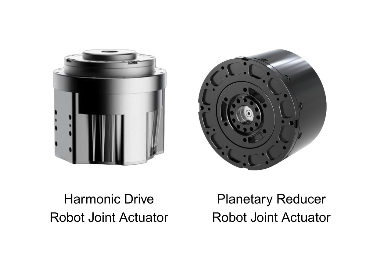
 What is robot joint actuator?How to Choose the Best Robot Rotary Joint Actuator?In core robot joint transmission solutions, planetary and harmonic rotary actuators each have their own strengths. Choosing the right type based on application requirements is essential to achieve the optimal balance between performance and cost.
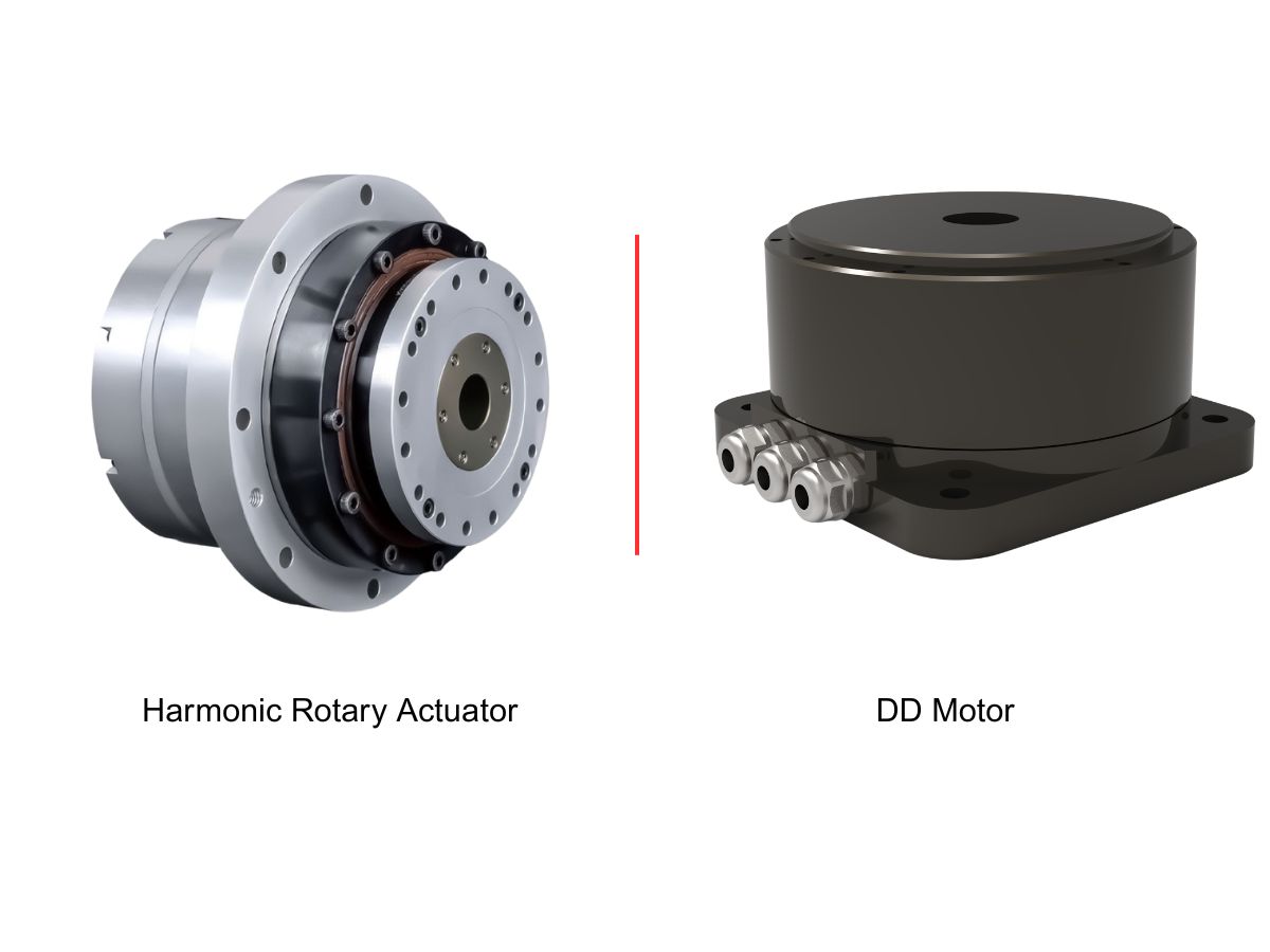
 DD Motors VS Harmonic Rotary ActuatorsThis article provides an in-depth comparison between Direct Drive (DD) motors and harmonic rotary actuators, covering their transmission principles, advantages and disadvantages, and typical application fields.
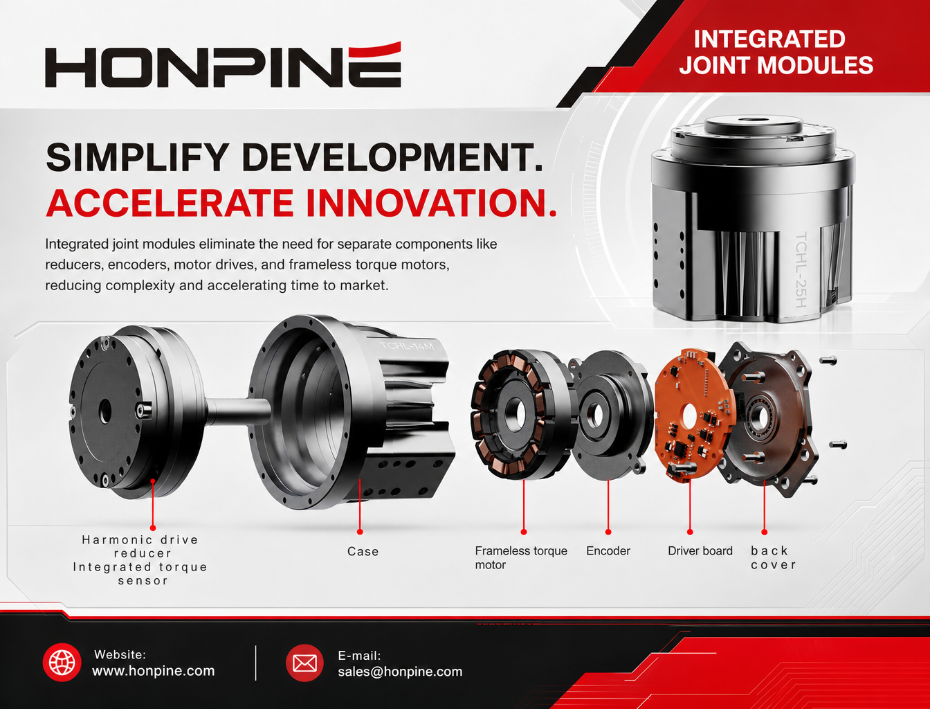
 OMG Ultra Compact Harmonic Drive Joint Module with Built-in Torque SensorHONPINE TCHL series harmonic drive joint module is a game-changing product that achieves disruptive improvements in multiple aspects such as lightweight design, integration level, and connection convenience. This article will analyze its revolutionary enhancements with you.
 The Role of Harmonic Drive Gears in Achieving 5–10 μm Accuracy in Dental Milling MachinesA dental milling machine is a CNC machining system used to directly process digital dental models into restorations such as crowns, bridges, veneers, inlays, and implant abutments. Dental milling machines require far higher operational accuracy and motion stability than ordinary equipment. This article explains how harmonic drive gear help dental milling machines achieve stable, continuous, and controllable operation.
 Why Are Harmonic Rotary Actuators Perfect for Medical Equipment?Harmonic rotary actuators (typically integrated systems consisting of a harmonic drive reducer, frameless torque motor, encoder, and optional brake) are regarded as key components in medical equipment. The core reason is that they simultaneously meet the most stringent medical requirements for precision, compact size, safety, and controllability. The following explanation is structured from three perspectives: technical characteristics, application scenarios, and medical value.
 High-Precision RV Reducers Perfectly Matched for Walking RobotsThe walking axis of a robot is a core component for power transmission and support. RV reducers provide extremely high rigidity, precision, and torque while maintaining a compact size and exceptional reliability, making them an ideal match for the demanding requirements of walking robot joints in terms of load capacity, impact resistance, and precision.
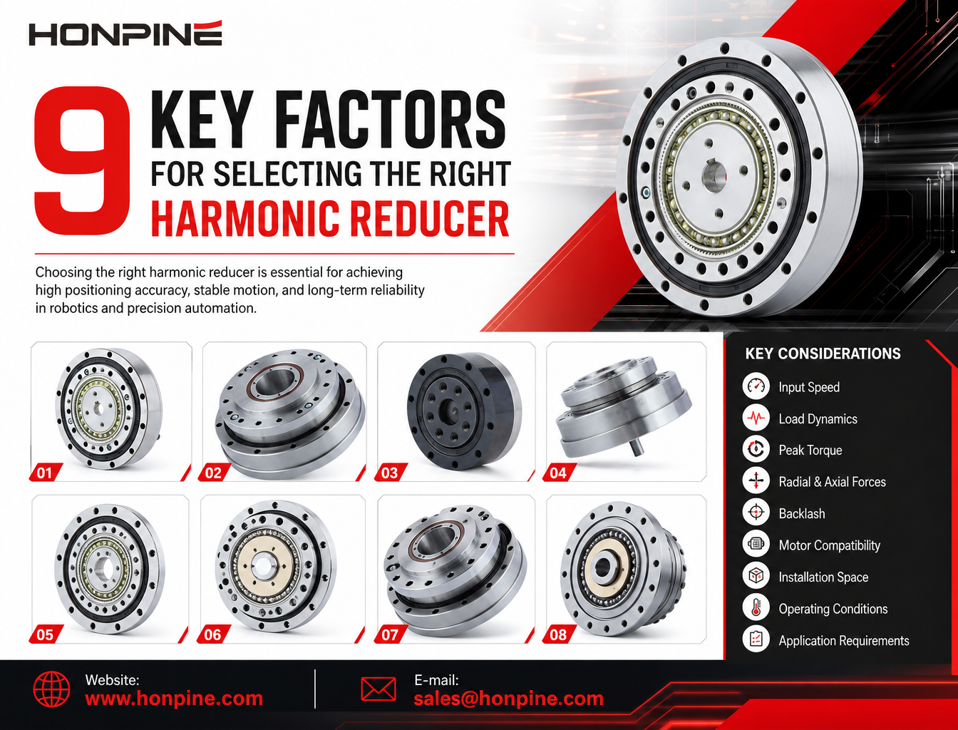
 How to Select a Harmonic Reducer: 9 Key Factors You Need to KnowWhy are more robotics companies choosing integrated robot joint modules instead of traditional distributed drive systems? As humanoid robots, collaborative robots, and rehabilitation exoskeletons continue to evolve, manufacturers are looking for more compact, lightweight, and easier-to-integrate motion solutions. An integrated robot joint module combines essential components such as a frameless torque motor, harmonic reducer, servo drive, encoders, and output bearing into a single assembly. This architecture can reduce mechanical complexity, simplify wiring, improve motion control integration, and shorten robot development cycles. In this article, Theodore Li, Technical Director at HONPINE, explains six key advantages of integrated robot joint modules and compares them with conventional distributed drive configurations.
 Why Are More Companies Choosing Integrated Robot Joint Modules?Integrated robot joint modules combine motors, harmonic reducers, servo drives, encoders, and output bearings into compact units. This article compares integrated and distributed drive architectures, exploring their differences in torque density, mechanical reliability, motion control, development efficiency, and practical robotic applications.
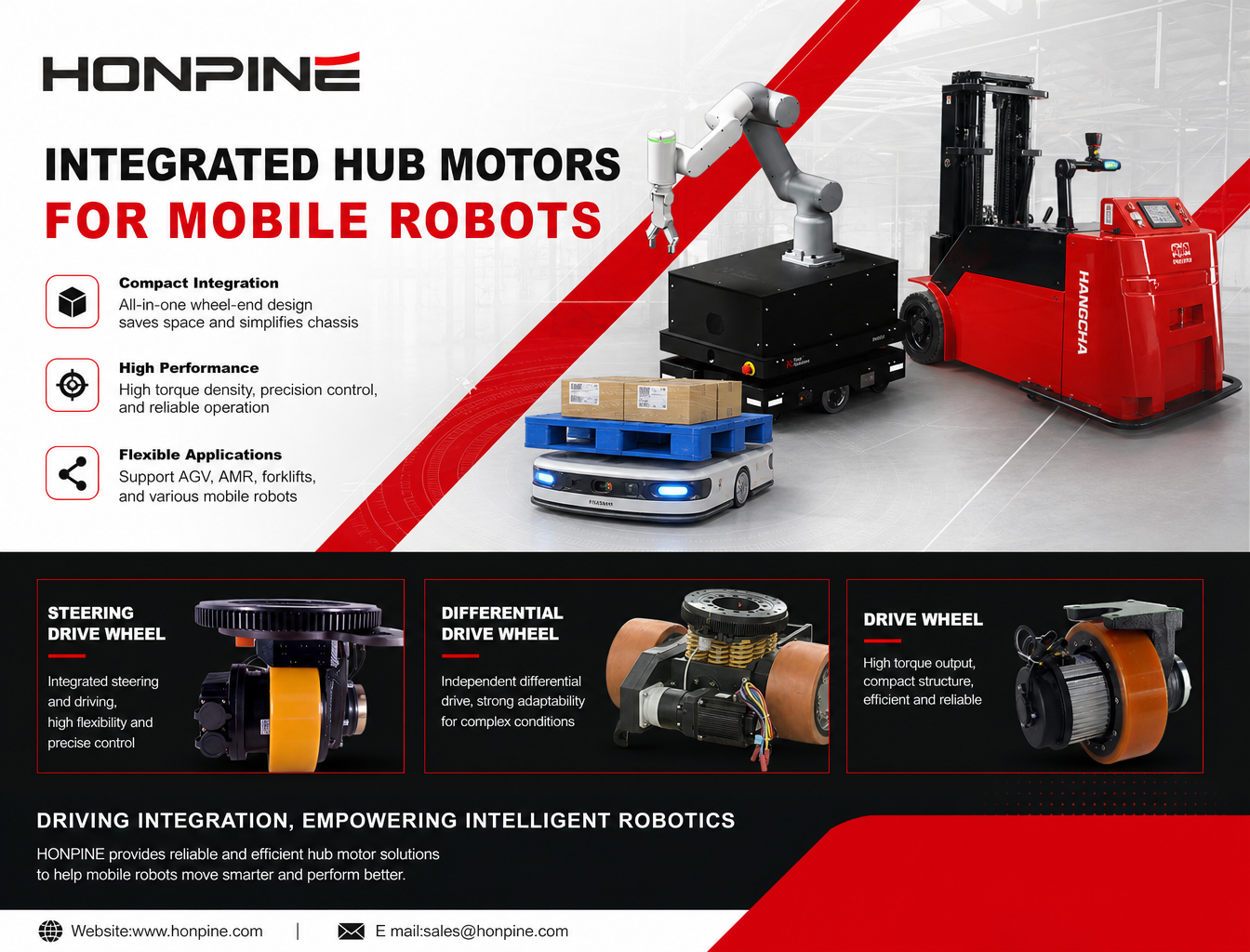
 Why Are More Robots Moving Away from Traditional Drive Systems to Integrated Hub Servo Motors?As mobile robots evolve toward autonomous navigation, flexible operation, and increasingly complex working environments, traditional distributed drive systems are facing new challenges. Separate motors, gearboxes, couplings, and transmission components can increase chassis complexity and limit available installation space. This is why more robot manufacturers are turning to integrated hub servo motors. By combining key drive components within a compact wheel-end unit, hub motors offer new possibilities for improving drive integration, motion control, and chassis design. In this article, we explore the key performance requirements of mobile robots, explain the advantages of integrated hub motors, and examine how HONPINE's Drive Wheels, Steering Drive Wheels, and Differential Drive Wheels support different AGV and AMR applications.
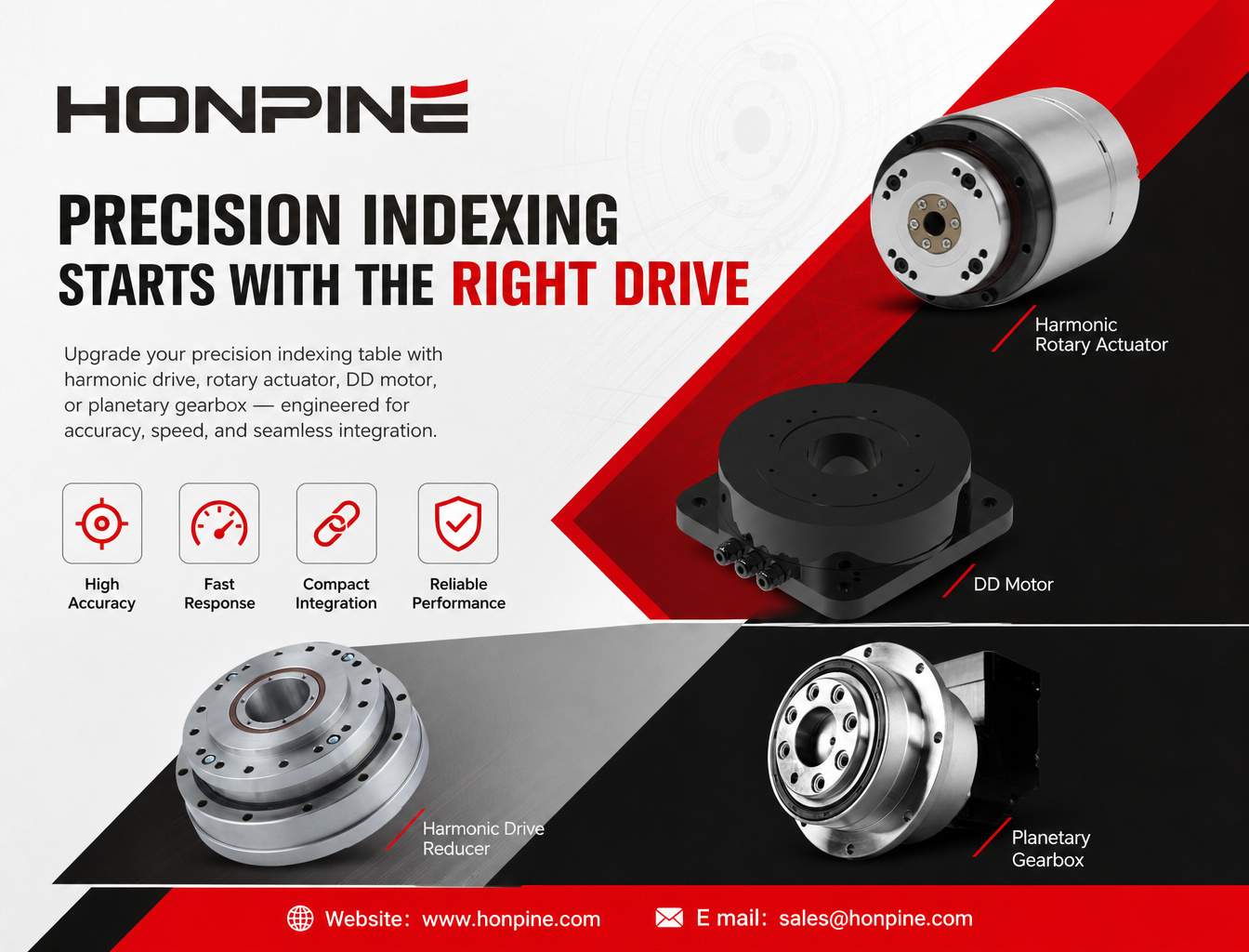
 How Can Precision Reducers, Harmonic Rotary Actuators, and Direct-Drive Motors Upgrade Precision Indexing Tables?How can manufacturers improve the accuracy, dynamic response, and integration of precision indexing tables? As flexible manufacturing continues to evolve, traditional transmission systems may face challenges such as backlash, long settling times, and complex mechanical integration. This article explores how harmonic drive reducers, harmonic rotary actuators, direct-drive (DD) torque motors, and planetary gearboxes provide practical upgrade solutions for different operating conditions. By matching the transmission architecture to positioning accuracy, indexing cycle time, load inertia, and installation constraints, manufacturers can develop more efficient and reliable precision indexing systems.
 Should Robot Manufacturers Develop Their Own Joint Modules or Buy Integrated Joint Modules?Should robot manufacturers develop joint modules in-house or purchase integrated joint modules? This article compares the advantages and disadvantages of both approaches, including development costs, technical ownership, supply chain stability, production efficiency, and long-term scalability. Learn why a hybrid sourcing strategy that combines in-house development with external procurement is becoming a practical option for humanoid robots, robotic arms, and embodied AI systems.
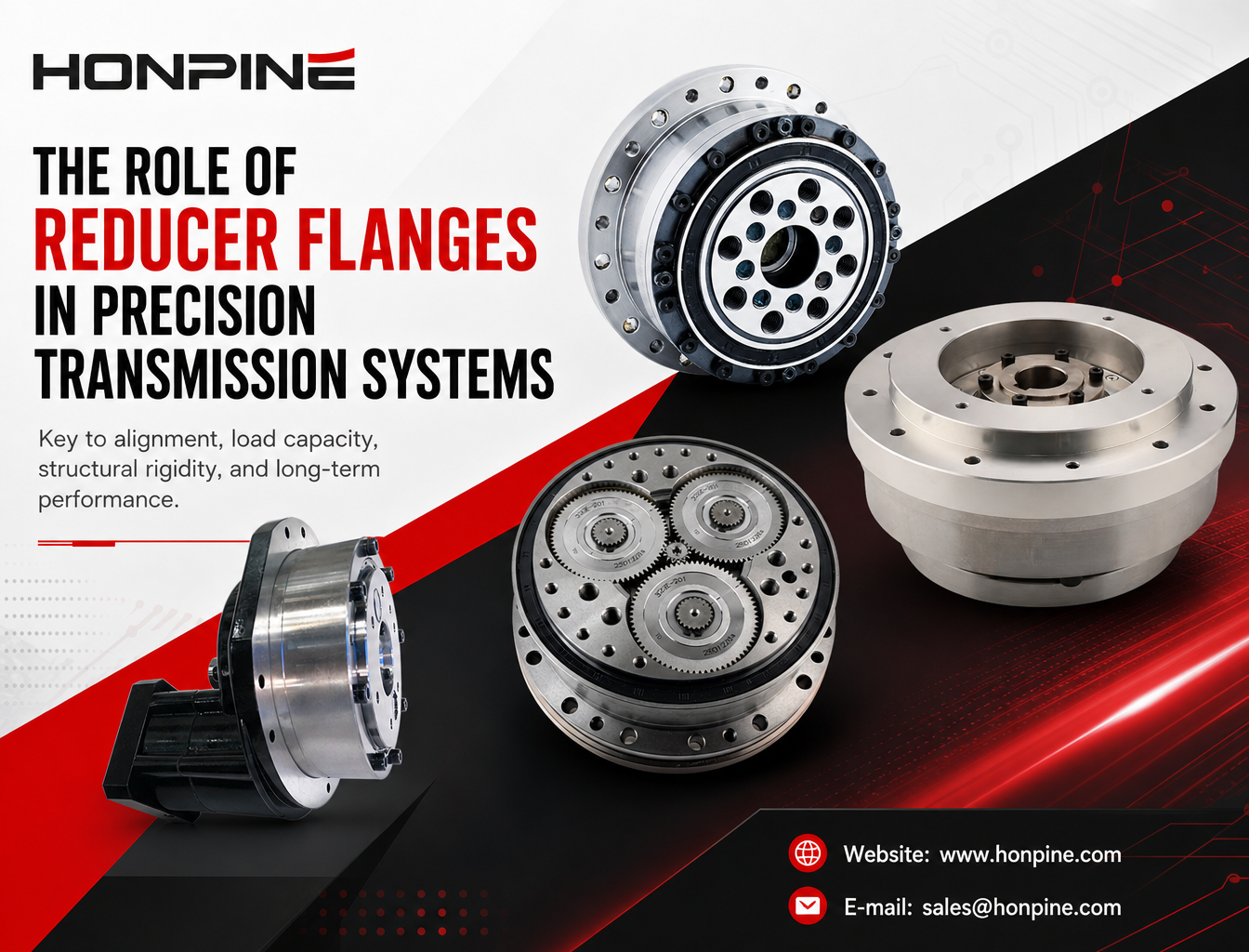
 Why Are Flanges on Harmonic and RV Reducers More Than Just Mechanical Mounting Components?A flange on a harmonic reducer or RV reducer is more than a mounting interface. It plays a critical role in alignment accuracy, load transmission, structural stiffness, and sealing performance. Even minor errors in flange design or installation can affect gear meshing, bearing life, and the overall reliability of a precision motion system. In this article, Theodore Li, Technical Director at HONPINE, explains the key engineering functions of reducer flanges and why they deserve careful consideration when designing and installing precision transmission systems.
Double Click
We provide harmonic drive reducer,planetary reducer,robot joint motor,robot rotary actuators,RV gear reducer,robot end effector,dexterous robot hand
 What is robot joint actuator?How to Choose the Best Robot Rotary Joint Actuator?In core robot joint transmission solutions, planetary and harmonic rotary actuators each have their own strengths. Choosing the right type based on application requirements is essential to achieve the optimal balance between performance and cost.
 DD Motors VS Harmonic Rotary ActuatorsThis article provides an in-depth comparison between Direct Drive (DD) motors and harmonic rotary actuators, covering their transmission principles, advantages and disadvantages, and typical application fields.
 OMG Ultra Compact Harmonic Drive Joint Module with Built-in Torque SensorHONPINE TCHL series harmonic drive joint module is a game-changing product that achieves disruptive improvements in multiple aspects such as lightweight design, integration level, and connection convenience. This article will analyze its revolutionary enhancements with you.
 How to Select a Harmonic Reducer: 9 Key Factors You Need to KnowWhy are more robotics companies choosing integrated robot joint modules instead of traditional distributed drive systems? As humanoid robots, collaborative robots, and rehabilitation exoskeletons continue to evolve, manufacturers are looking for more compact, lightweight, and easier-to-integrate motion solutions. An integrated robot joint module combines essential components such as a frameless torque motor, harmonic reducer, servo drive, encoders, and output bearing into a single assembly. This architecture can reduce mechanical complexity, simplify wiring, improve motion control integration, and shorten robot development cycles. In this article, Theodore Li, Technical Director at HONPINE, explains six key advantages of integrated robot joint modules and compares them with conventional distributed drive configurations.
 Why Are More Companies Choosing Integrated Robot Joint Modules?Integrated robot joint modules combine motors, harmonic reducers, servo drives, encoders, and output bearings into compact units. This article compares integrated and distributed drive architectures, exploring their differences in torque density, mechanical reliability, motion control, development efficiency, and practical robotic applications.
 Why Are More Robots Moving Away from Traditional Drive Systems to Integrated Hub Servo Motors?As mobile robots evolve toward autonomous navigation, flexible operation, and increasingly complex working environments, traditional distributed drive systems are facing new challenges. Separate motors, gearboxes, couplings, and transmission components can increase chassis complexity and limit available installation space. This is why more robot manufacturers are turning to integrated hub servo motors. By combining key drive components within a compact wheel-end unit, hub motors offer new possibilities for improving drive integration, motion control, and chassis design. In this article, we explore the key performance requirements of mobile robots, explain the advantages of integrated hub motors, and examine how HONPINE's Drive Wheels, Steering Drive Wheels, and Differential Drive Wheels support different AGV and AMR applications.
 Why Are Flanges on Harmonic and RV Reducers More Than Just Mechanical Mounting Components?A flange on a harmonic reducer or RV reducer is more than a mounting interface. It plays a critical role in alignment accuracy, load transmission, structural stiffness, and sealing performance. Even minor errors in flange design or installation can affect gear meshing, bearing life, and the overall reliability of a precision motion system. In this article, Theodore Li, Technical Director at HONPINE, explains the key engineering functions of reducer flanges and why they deserve careful consideration when designing and installing precision transmission systems.
 How Should Manufacturers Upgrade Harmonic Joint Modules for Robotic Arms and Embodied AI in 2026?For engineers planning a robotic system upgrade, the right joint module depends on more than a single specification. EtherCAT synchronization, output-side position feedback, real-time torque measurement, continuous torque capability, and integrated safety functions must work together to meet the demands of the application. By evaluating these factors as a complete electromechanical system, manufacturers can make more informed decisions about joint module selection, integration, and long-term performance.
 How Do Planetary Gearboxes Reduce Speed and Increase Torque in High-Precision Automation Equipment?How does a planetary gearbox reduce speed while increasing torque in high-precision automation equipment? By combining a sun gear, multiple planet gears, and an internal ring gear, a planetary gearbox delivers compact, efficient power transmission for applications that require controlled motion and reliable torque output. From industrial robots and CNC machinery to automated assembly systems, selecting the right gearbox involves more than choosing a reduction ratio. This guide explains how planetary gearboxes work, their key advantages, common applications, and practical selection considerations to help engineers identify a suitable transmission solution.
 Should You Choose a T-Type or Straight-Type Harmonic Joint Module for a Collaborative Robot?Choosing the right harmonic joint module is essential when designing a compact, high-performance collaborative robot. Should you use a TCHL straight-type or an HTS T-type harmonic joint module? Although both configurations can support precise robotic motion, their different output flange geometries affect installation space, link connections, cable routing, and mechanical integration. In this guide, Theodore Li, Technical Director at HONPINE, explains the key differences between the two designs, their advantages and limitations, and how to select the most suitable configuration for your collaborative robotic arm.
 The Complete Harmonic Joint Actuator Solution for Humanoid Robots: HPJM Series Selection GuideA complete guide to selecting harmonic joint actuators for humanoid robots. Explore HONPINE HPJM models for wrist, elbow, shoulder, waist, hip, knee, and ankle joints, with practical considerations for torque capacity, reduction ratios, dynamic response, and holding brake configurations.
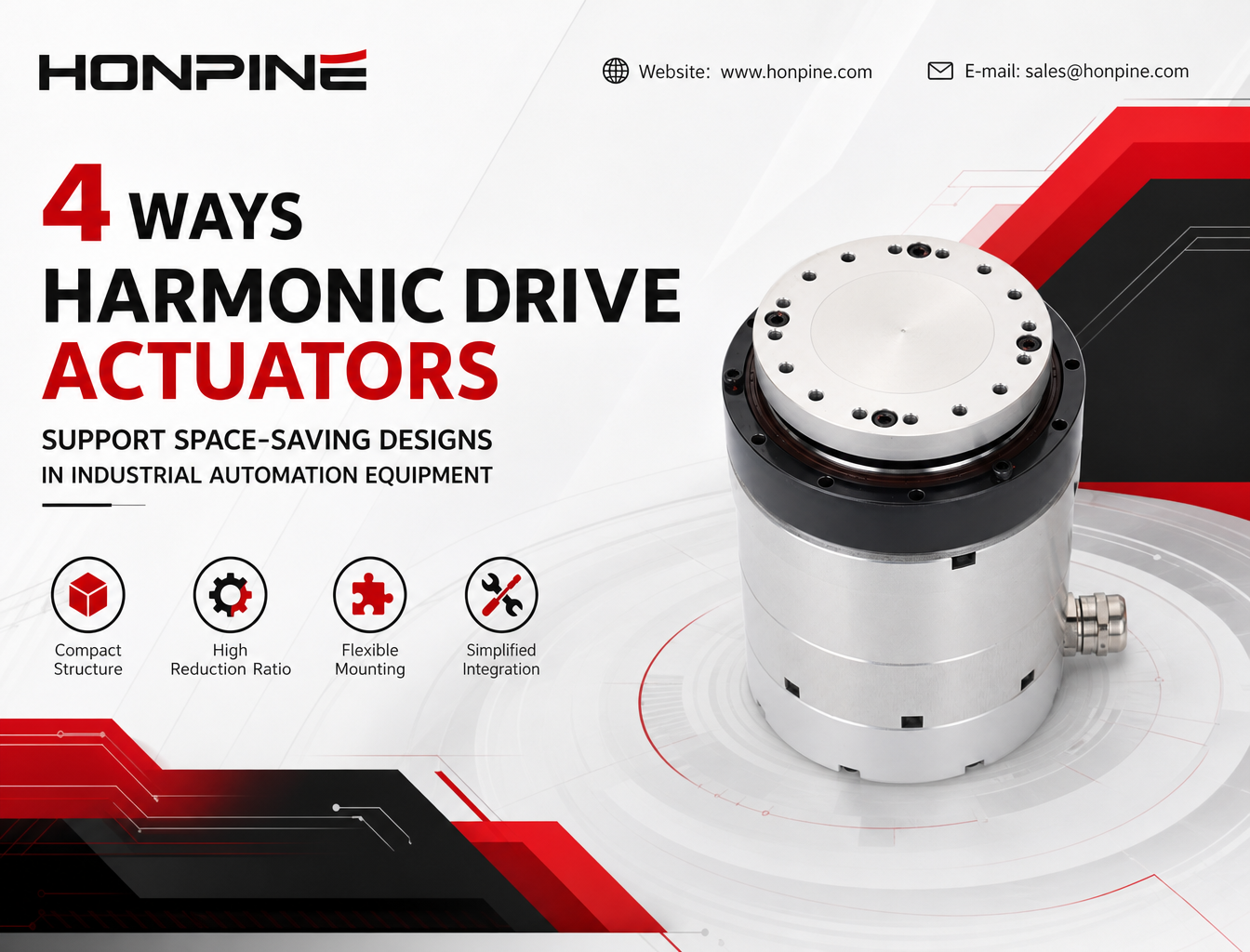
 Why Are Harmonic Drive Actuators Ideal for Space-Constrained Industrial Automation Equipment?In modern industrial automation, limited installation space often makes mechanical design more challenging. Harmonic drive actuators offer a compact motion-control solution by integrating key drive components into a single unit. Their high reduction ratios, streamlined mechanical structures, and flexible mounting options can help equipment manufacturers reduce space requirements, simplify assembly, and optimize internal layouts. This article explores four ways integrated harmonic drive actuators support space-saving designs in industrial automation equipment.